RANK ALDIS TUTOR II -------------UPGRADES AND MODIFICATIONS
Mods to the Tutor II are always welcome, and detailed here are some of the more common mods to make this workhorse better. Add a Power inlet. Upgrade to higher power lamp. Fit a hanging bracket. Use custom attachments. Add remote control functions.
Dependant on the revision of projector you may have a power cord attached to the projector, fitting an IEC power socket is easy and makes life a little better for using and transporting the Tutor II - here's how. |
|||
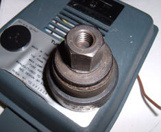
 To make the hole required for the socket, I am using a chassis punch. These are commercially available but you can do the job with drill and file if you are carefull. To make the hole required for the socket, I am using a chassis punch. These are commercially available but you can do the job with drill and file if you are carefull. |
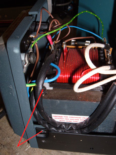 |
 The transformer bolts. Loosen off or remove completely to free the transformer from the rear casting. The transformer bolts. Loosen off or remove completely to free the transformer from the rear casting. |
|
| Above - location of screws/bolts to remove and loosen. The transfomer may differ, but the bolts are in the same place. Do both sides. | |||
 |
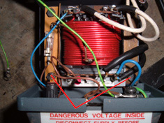
Once the transformer bolts and side screws are done, remove the two screws underneath and the rear casting can be pulled away to allow access to the mains cord and wiring as shown on the right. If you have cage nuts mounting the transformer as shown-remove them and fit them into the clots of the rear casting indicated, it makes assembly easier. | 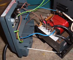 |
|
| Next job is to chop the mains cord and remove the cable gland holding it. Leave 1 or 2 inch of the lead as we are using this to wire to the connector when fitted. Shown far right is the cutter assembled thru the hole left by the cable gland, thightening this will cut the hole. Alternatively mark out and cut the hole with drill and file to exact size | 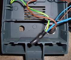 |
 |
|
 |
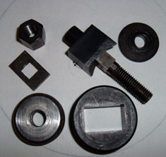
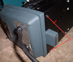
Shown left is the resulting hole cut ready for the IEC connector, the size of hole depends on the make and type used. Here I am using a Bulgin push fit type. On the right you see the connector clipped into the rear casting. If using a clip type I recommend adding a little glue around the connector to ensure it is really firm. | 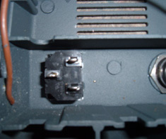 |
|
 |
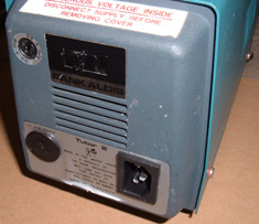 |
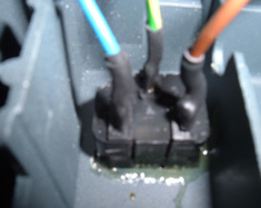
Far left: Use the existing wires, cut to length and soldered to the connector. I recommend two applications of heat shrink sleeve to cover the connections for good insulation. Centre image shows the power connector on the re-assembled projector. Test the electrics or get a qualified person to check out your wiring before using the projector. | |
:::: NEXT UP ::::: CONTROL LIGHT OUTPUT WITH A DMX CONNECTION::::
|
|||
:::: ALSO ::::: FIT A HANGING BRACKET (USES OPTI SOLAR 250 STAND):::: CLICK HERE |
|||
| Work in progress --- check back later | |||
A note about copyright......I have tried to find publishers or anyone i can get, but some of this content is very old now. If you see your work here and it's an issue, contact me. I will either change, acknowledge or remove it. (site policy here)
Copyright © M.Ginda 2018