SERVICE INFO AND SCHEMATICS FOR DJ Disclite MKII
|
|
 |
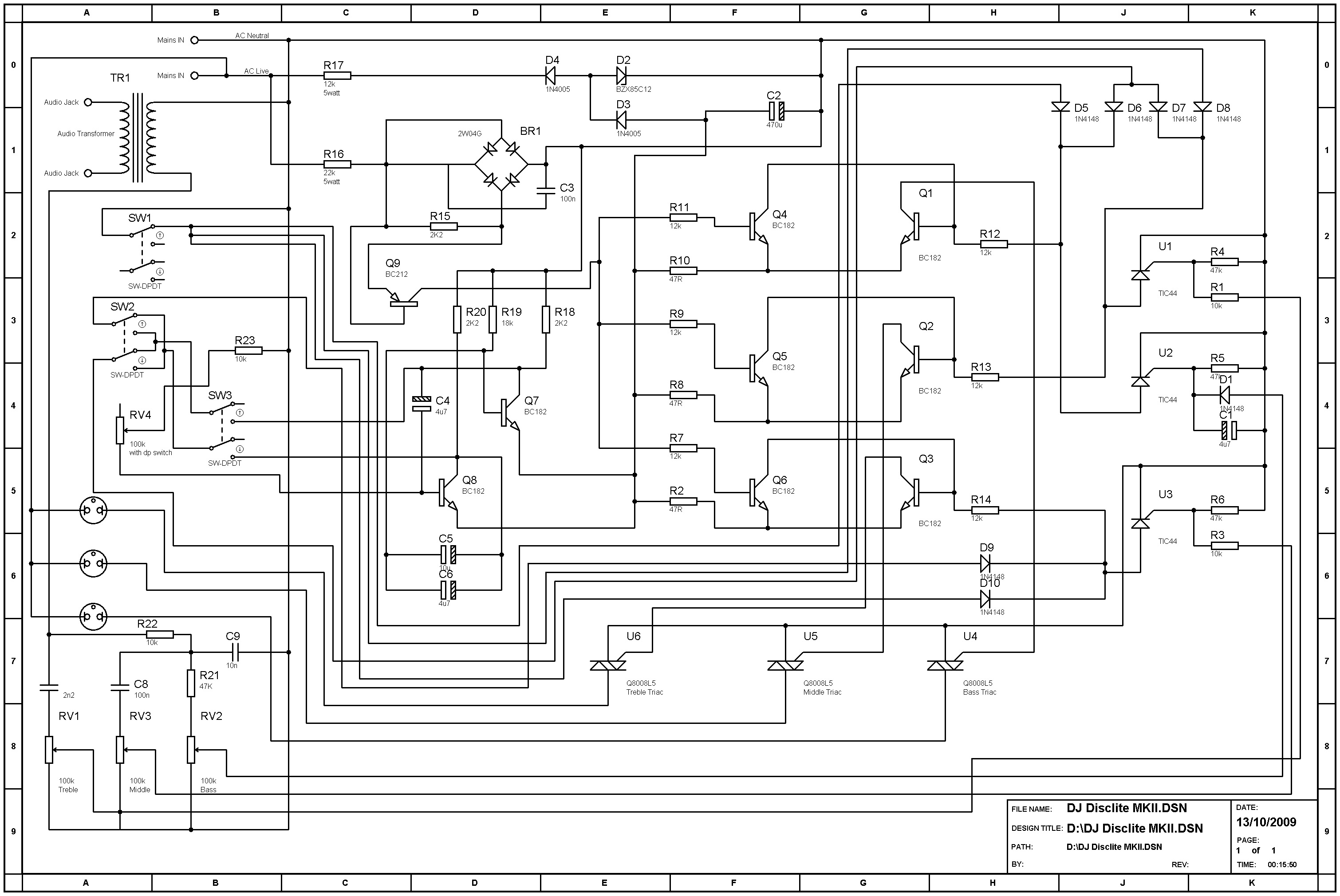 |
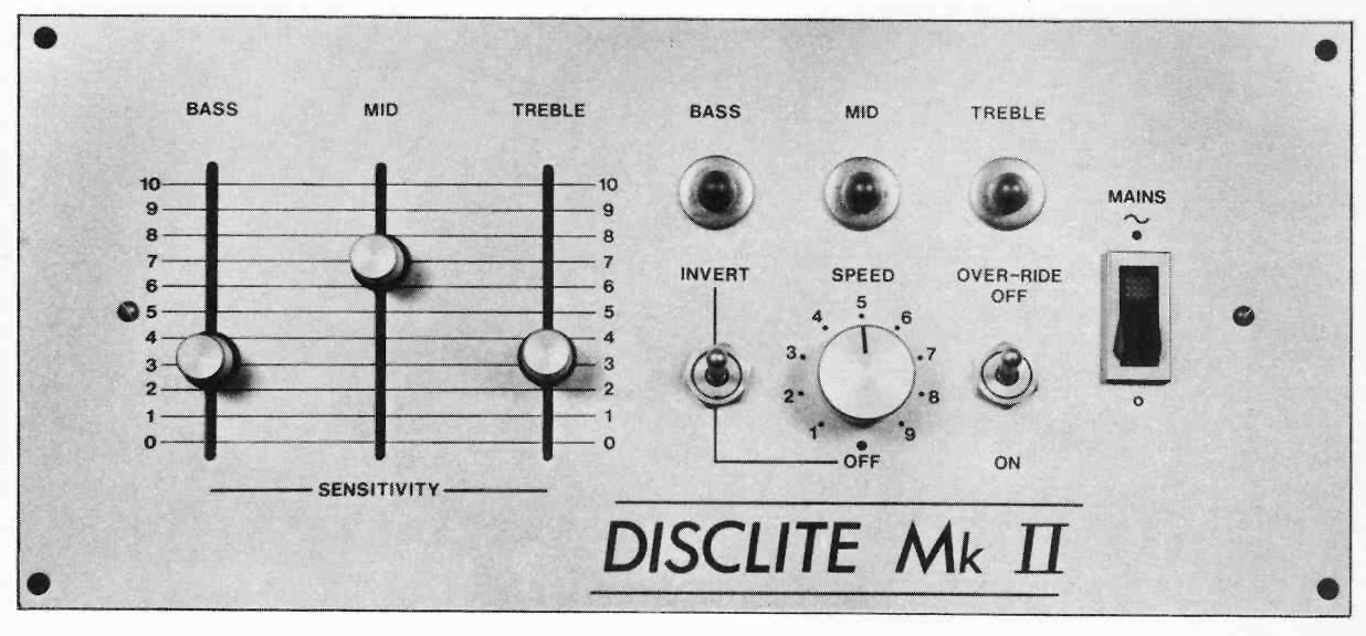
| Above left is the front panel layout. This was also available in an anodised black finish. to the right is the circuit diagram of the unit. The placement of components on the page has been arranged to reasonably match the physical location of that part on the printed circuit board. To view the image full size, click the image. The electronics are housed in a 'u' shaped section attached to the front panel, this has an aloy rear panel with power inlet cable, audio input jack socket and 3 bulgin 3pin mains connectors for channel outputs. The three indicators are 240v neons, the rotary control also has a dpco switch, bothe switches are dpco types. There is a perforated cover to this section which is all similar to the DJ disclite 32L shown elsewhere on this website. | |
 |
 |
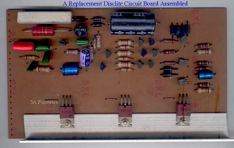 |
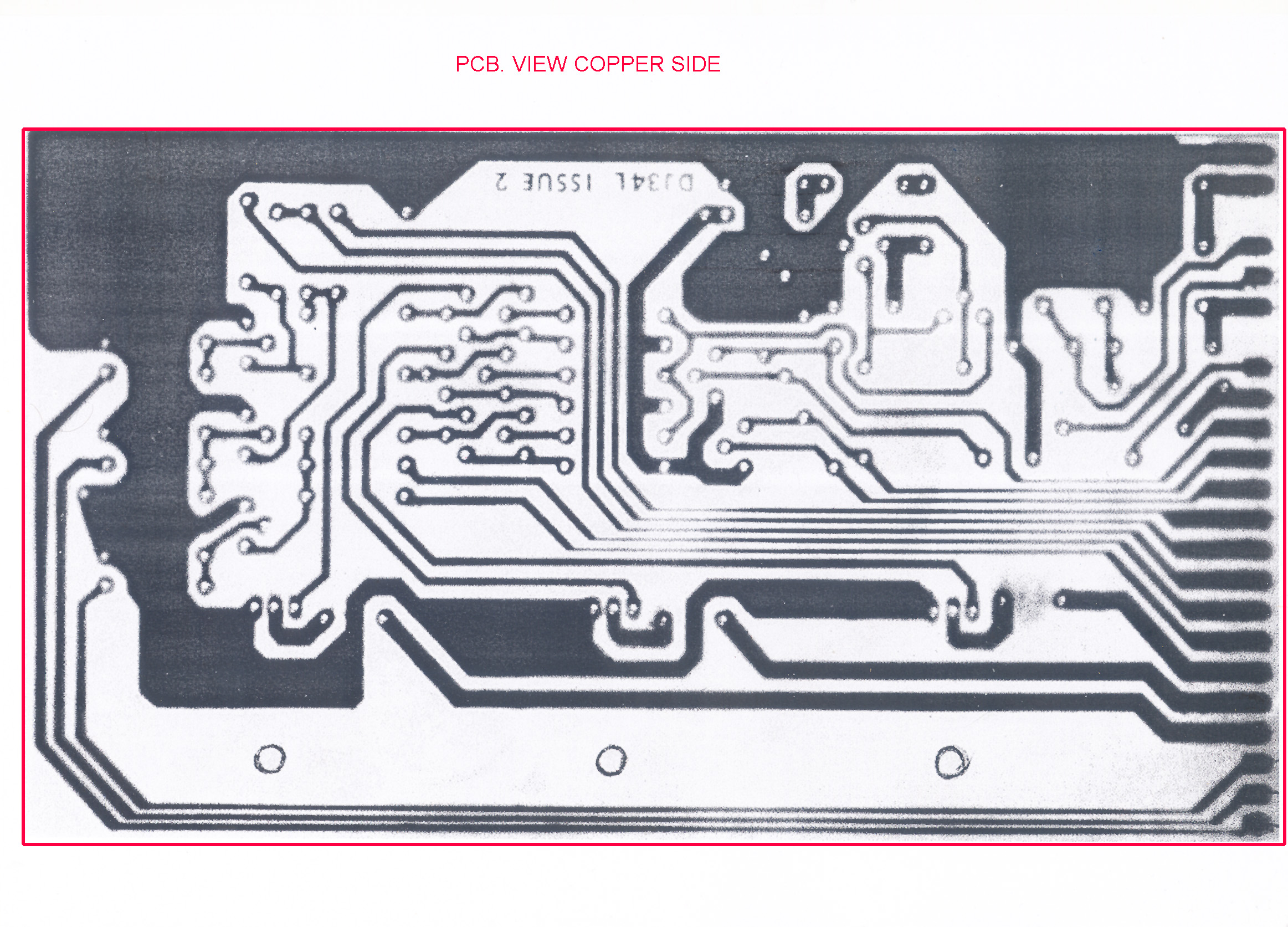
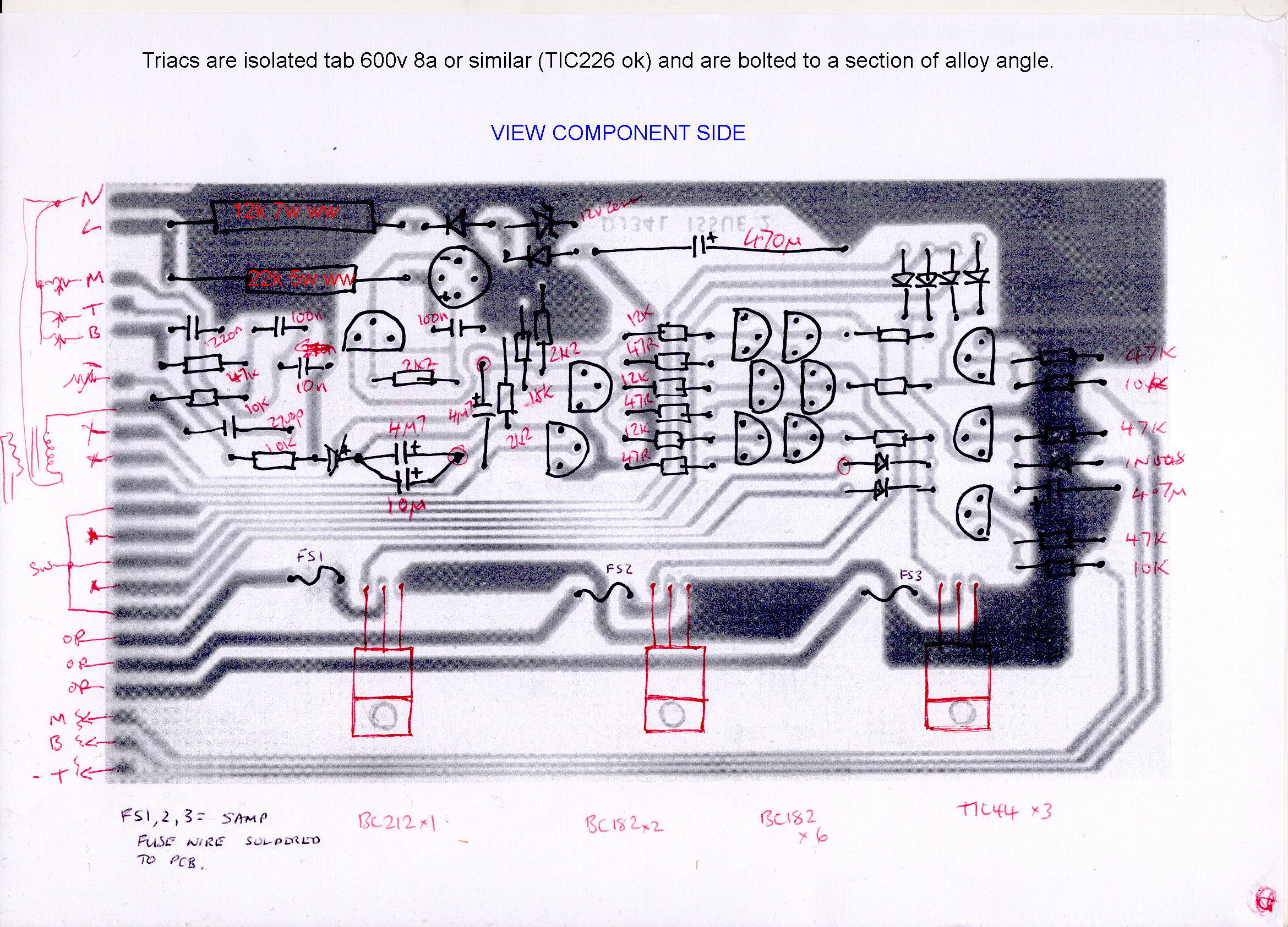
Shown Left is an assembled replacement pcb made in the early 80's to repair a burned out unit. Never used but presented here as a sample to show component placement. Note the alloy angle used to bolt the assy to the base and provide a heat sink. Also note the 5Amp fuse wire soldered into the pcb next to each triac...a cost cutting and possibly safety feature, though i would now recommend 20mm fuseholders with ceramic qb fuses. |
| .It must be noted that this equipment has a sound input intended for connection to equipment of the day, so we are connecting to amplifiers with typically 50 or maximum 100watt rms outputs. | |
|
|
Copyright © M.Ginda 2018